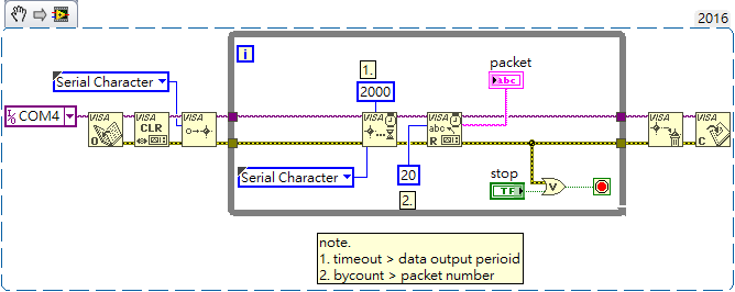
Serial Time Out Labview 2016
[modbus] Connection timeout with modbus TCP slaves should be. 2016 9 comments. The read timeout of serial slaves is more like the SO_TIMEOUT parameter.
I would prefer using Serial but there is TCP option as well. It looks like the equipment I am using have the option to select between RTU and ASCII, but the default is RTU.
Axis camera station license. I ran the example VI in the library and I am getting 'Timed out' errors. I'm new to this so not really sure where to start troubleshooting. If there's an existing code that someone has that works on their end, then it will be helpful for me to troubleshoot it. I have attached a list of register defintion here. I know the serial settings.
I do not know how to pass info to the unit and receive feedback. I'm not sure how to format the command or how to incorporate it with the modbus library vi. I ran the example VI in the library and I am getting 'Timed out' errors. History of circle kabaddi game in hindi.
I'm new to this so not really sure where to start troubleshooting. If there's an existing code that someone has that works on their end, then it will be helpful for me to troubleshoot it. I've used to example/library from the NI website with success. The code does work. Timeout out with serial would tend to indicate to me that there was no response. You should get error messages if you are talking to the device. My first suggestions would be physical.
Are you plugged in on both ends? Are you plugged into where you think you are? Do you have a null-modem cable when you need a strait-through or visa-versa? Is the device on? Next thing to find out is if the unit your trying to communicate to is a master or slave. I'm guessing its a slave. The supports RTU and ASCII.
If you have Labview DCS or RT, you could use the. I know that Modbus I/O Servers supports RTU but have never used it myself. The examples that ship with the NI Modbus Library are probably not going to work without some modification to the reading and writing. I would first try to read 1 word at the first address and see if you can get some data from the device. You could use a known Modbus master like to help you troubleshoot the communication. Although the register def file is pretty cryptic (a nice secret decoder ring would be nice ), it looks like address 1 through 35 can be accessed with a read function and 201 through 203 from a write holding registers command.
I highly suggest you read up a bit on the basics of Modbus first before you dive in and try to communicate. The focus here would not be the entire protocol but just start with understanding the memory map in Modbus and some of the basic function calls. It could be that addresses 1 through can only be accessed from a read input registers command. The equipment you have should have documentation describing which modbus functions should be used to communicate.

Here a good start on Modbus info: Edited April 29, 2010 by David Wisti. Here is a screen shot of the MB Serial Example Master vi. It times out trying to read discrete inputs. This is the initial hurdle and I'm also stuck on how to send or commands to read/write. Such as in the attached text file above, 005 is to read the software status, how should this command be formatted and inserted in the code. My best guess is you need to set the address, change from input registers to holding registers, and set the correct number of words you want to read. The Modbus spec (see David Wisti's link) is pretty readable and does contain the error codes you'll get back from the device.
One caveat about Modbus addresses is the address you need to request may not be the one documented by the manufacturer, but it will be near that address (+/- a couple); I've found this to be the case on Festo and Cuttler Hammer equipment (to boot the PLC and PC request different addresses for the same register. My best guess is you need to set the address, change from input registers to holding registers, and set the correct number of words you want to read. The Modbus spec (see David Wisti's link) is pretty readable and does contain the error codes you'll get back from the device.